How to install Electric

How to install: Electric operated Roller Shutters

This section will guide through the installation process of our Domestic, Cyclone, Security and Light Commercial range of shutters, the process is almost the same for all four shutter types, with modification needed to the Cyclone and Light Commercial and Security, which is listed at the bottom of this page.

Tools required:

  • Spirit level.
  • Drill.
  • Riveter
  • Hammer.
  • 10mm drill bit.
  • 5mm drill bit.
  • 5 or 6mm Masonry drill bit depending on wall plug size chosen, and Stainless Steel screws to suit. For timber frame windows, just Stainless Steel screws.
  • Electric components: 1 head box, 2 guides, 2 guide legs, 10mm coloured guide plugs and rivets.

Step 1.

Mark the top horizontal position of the Roller Shutter on the wall above the window. On this line mark the width of the shutter. From these 2 marks, vertically level down each side of the window. You will now have the out line of the Roller Shutter marked on the wall. At this stage you can check that this is central to the window and is exactly horizontal and vertical — This Is Most Important!

With the out line of your shutter now marked on the wall, you can now decide the best point of entry for the mains power and pre drill the hole before installing (if required).

In-Reveal is the same principle, but your window is your horizontal and vertical position. Still check that they are exactly horizontal and vertical — This Is Most Important!

Step 2.

Measure the depth of the head box Then from the top horizontal position of the Roller Shutter which you have marked on the wall, measure this distance down each side. This will then give you the position for the top of the guide on each side of the window. For In-Reveal installation you can now cut the guide to the exact length, and angle of the sill.
Modification required for the Cyclone Roller Shutters
The HDF-R Restrained Guide must be modified, this should be done at (this procedure is not on the video see link below) HDF Restrained Guide must be modified.

Step3
Hold the guide in the 2 positions marked. Top of guide position (as in step 2) and the vertical guide position (as in step 1). You can now mark the best position to fix the guide to the wall and these marks can be transferred to the other side guide. You can now drill through the front and back of the guide; the drill size is determined by the size of screw you use. The front of the guide will need a 10mm hole in which the 10mm coloured guide plugs are inserted – this then covers up the fixing points.

shutter56

For In-Reveal: The fixing holes are drilled from the curtain side 10mm to the outside 5mm. No 10mm coloured plug is required.

shutter57

Step 4.

The head box comes with pre drilled holes to attach the head box cover after installation. The guide legs can now be slid into position, (die cast legs that fit onto the bottom corner  of each side of the Head box, and  connect the main assembly to the guides) remove the rubber rings first that hold the plastic box end insert, this box end insert helps guide the curtain from the head box down into the guides. Then slide the guides on each side leg. Carefully place the Roller Shutter on the out-line marked on the wall and mark your fixing points.
Then drill and plug the wall if masonry; if it is a timber wall, just a pilot hole to suit the fixing Stainless Steel screws.

Step5
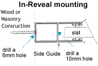
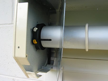
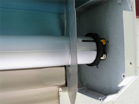
Carefully place the Roller shutter next to the window, then feed the cable from the motor (if required) through the hole you have pre drilled in Step 1, this will help the electrician. Raise the shutter to the outline of the marked on the wall and then screw it to the wall.
For On-Wall Installation then insert the 10mm coloured guide plugs.

Step 6

Unwrap the curtain and place the bottom bar of the curtain into the guides on each side.

Please note: The curtain will not move, until the motor has power to turn the axle.

Step 7

Contact a qualified electrician!

Step 8

At the motor end of the axle you will see a Yellow and a White button. These are to set the stop position at the fully open and fully closed position.

shutter58

SOMFY electric motor on
left side of the axle
White button is to set the down limit, the yellow button is to set the upper limit.

t20 battery replacement motor

SOMFY electric motor on
right side of the axle.
Yellow button is to set the down limit, the white button is to set the upper limit.

With both buttons depressed, you can now commence to set your ‘up’ and ‘down’ limits. It would be advisable to begin the limit setting with the curtain in the middle position and practice setting the limits until you are confident and comfortable with this procedure.

Setting the lower limit position:

Power the motor down and stop the product at the Down limit position. Press the corresponding limit button on the HiPro motor until the button springs up.
The lower limit positions has been set.

Box End Entry Roller – Kit

Setting the up limit position:

When setting the Up stop limit all of the bottom bar needs to protrude out of the head box.

Power the motor up and stop the product at the Up limit position. Press the corresponding limit button on the HiPro motor until the button springs up.
The upper limit positions has been set.

shutter61

Please note: If the shutter height limit is not set correctly, the bottom bar of the curtain has a bottom bar V stopper each side, which stops the curtain from going completely into the head box, but this causes the motor to jam and stop, this should be avoided and the up limit set to stop the curtain before this happens.

Please note: The Box Locking System must be set at the correct position. Please read
The Box Locking System and the Slat locking System

Step 9.

When the curtain is in the down position you will be able to fix the head box to the wall, this should be done on each side through the head box end plate.

Step 10.

Box End Entry Roller – Kit This is only supplied with Extra Large shutters in the Cyclone, Security, and Light Commercial range, this will not be supplied with smaller shutters in the range. Box End Entry Roller – Kit modifications.


Step 11.

Rivet the electric motor cover plate on.
Then fix the head box cover on and you are done!.

Please Note:
Although 90% of windows have sills, if your windows don’t, then don’t despair! We have a solution to that.
We can supply a false sill which is needs for the curtain to fully close down on.

shutter62

The aluminium sill can be the same colour as the head box and guides and come in 3 sizes

24mm x 22mm $6.00
24mm x 46mm $8.50
24mm x 77mm $12.00

To order a sill send an email and request a sill immediately after you place your order
I will then send you a PayPal request for payment.

Modification required for the Cyclone, Light Commercial, and Security.

Cyclone Modifications: The HDF-R Restrained Guide must be modified, this should be done at Step 2 (this procedure is not on the video see link below) HDF Restrained Guide must be modified.

Cyclone Modifications: To comply with the Cyclone Rating the shutter must be fitted with a Bottom Guide to the full width of the exposed curtain, allowing the curtain bottom bar section to close down into the bottom guide section, Step 3. This information and other fixing requirements can be found at this link, a must read item. Australian Standard AS / NZS 1170.2 – 2002

Box End Entry Roller – Kit This is only supplied with Extra Large shutters in the Cyclone, Security, and Light Commercial range, this will not be supplied with smaller shutters in the range. Box End Entry Roller – Kit modifications.